Reading data from EEPROM without desoldering
Introduction
In IoT/Hardware security it is common practice of dumping firmware/bootloader data inorder to perform reverse engineering for closed source system applications.
Well known easiest way is to download .bin/.zip (packed firmware) files from device manufacturer’s website which they provide to end users for firmware upgrade operations. And later us hackers/security researchers throw these files to reverse engineering softwares such as binwalk to check it’s contents and extract the needed stuff. But there are some challenges to this method as more and more embedded device manufacturers are becoming aware of it:
- Availability: Some companies only allow to obtain firmware files for update if you are a registered parnter with them and you need to get login creds or device manufacturer is too lazy that never provided any update for the device so you can’t find those file anywhere online.
- Encryption: It’s been becoming a big headache lately since companies have started pushing strongly encrypted firmware files with unbrekable symmetric ciphers such as AES which makes reverse engineering task nightmare. There are ways to find encryption key in previous updates of firmware CheckThisOut but if it is stored on hardware part of the secure element chip (STM32) then no way you can retive the key.
The new easy way
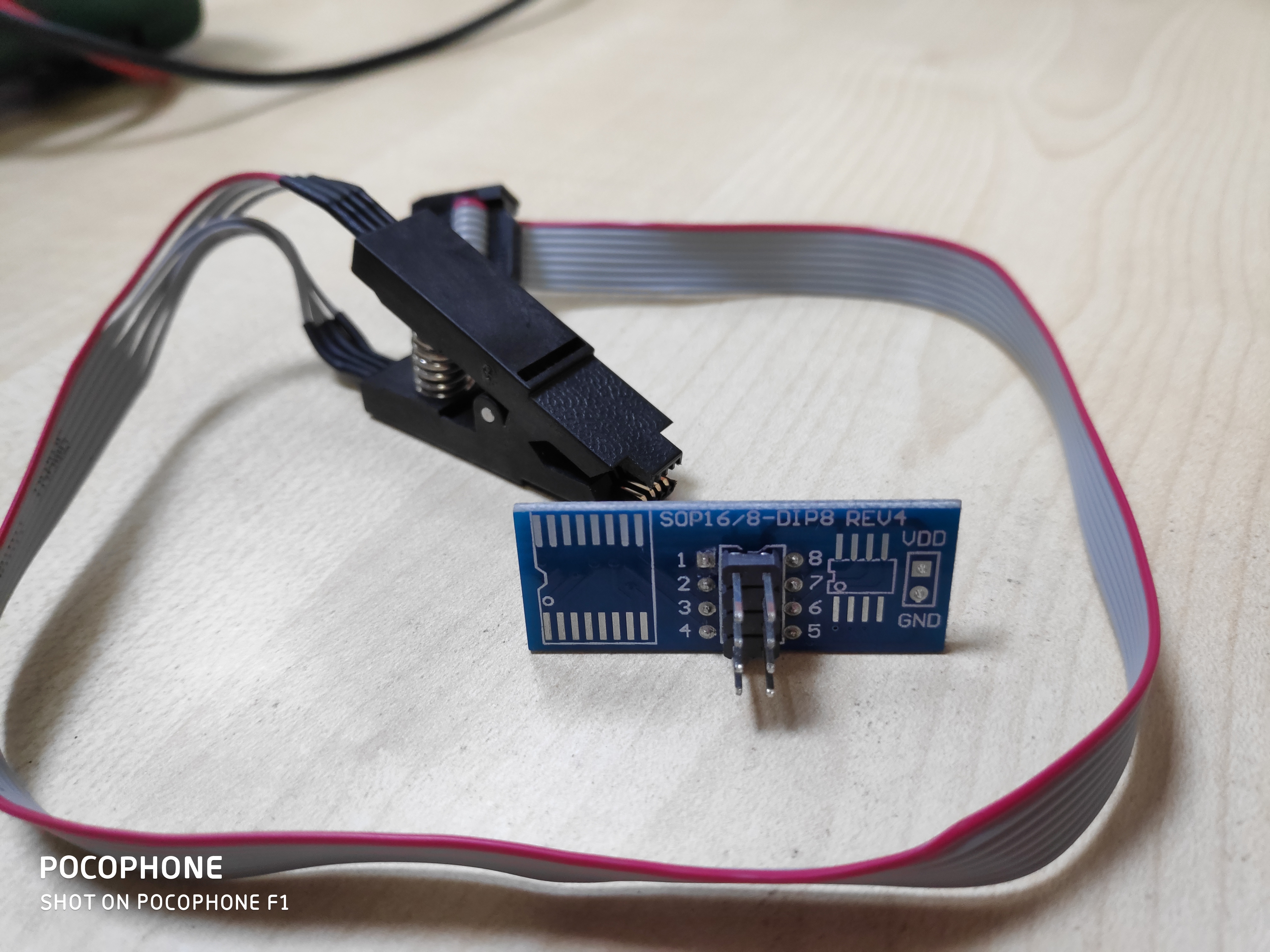
Meet SOIC8, it’s programming chip which allows embedded software developers to test EEPROM chips not just you can write changes with it but also read existing data from there or you can say dump the firmware easily. You can order one with clip adapter from AliExpress for roughly around 5$. Behind SOIC8 this there are 8 more pins which will be used to connect SPI communication device (In our case RaspberryPi).
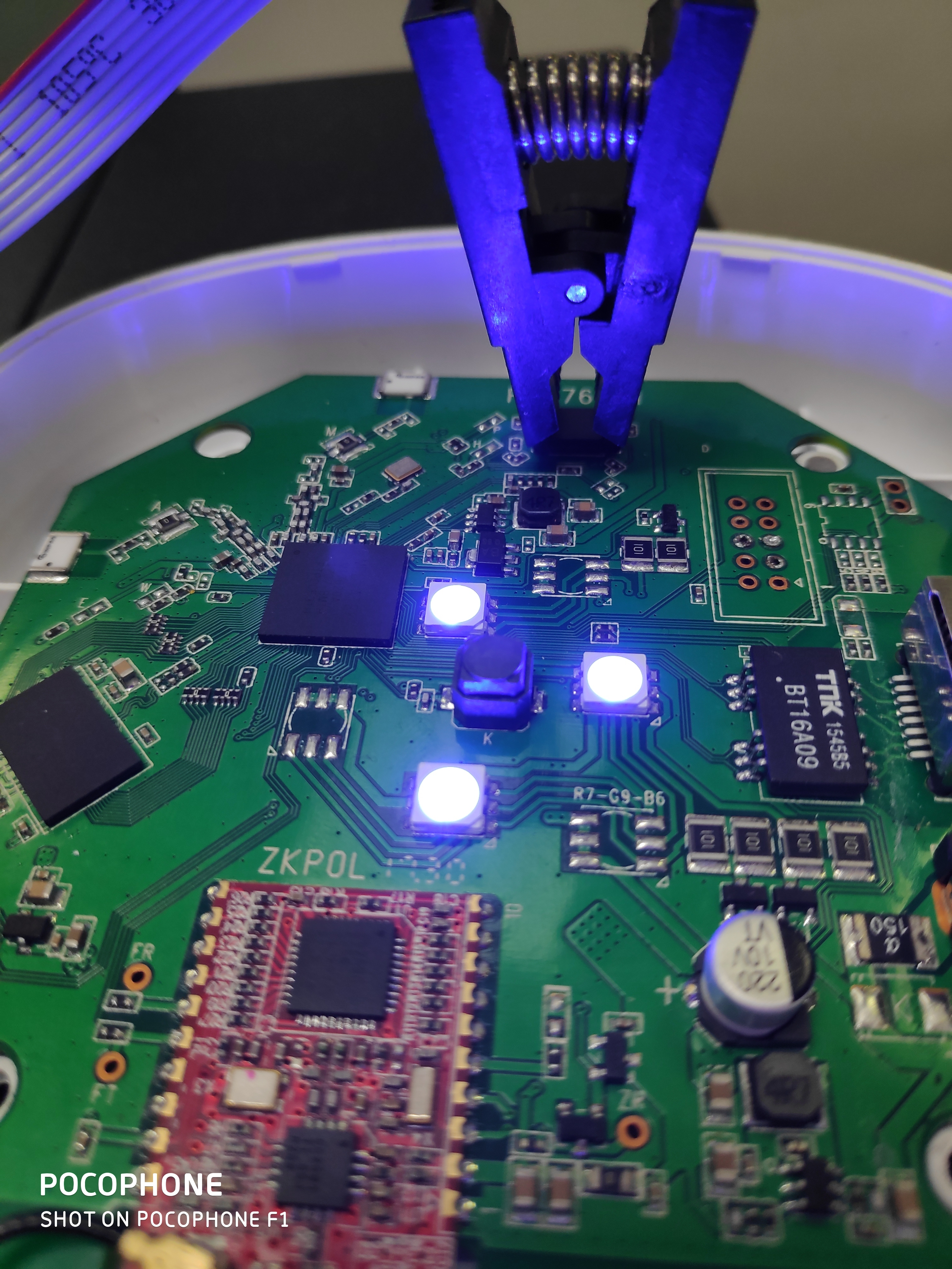
Now next step is to indetify model number of our EEPROM chip and it’s orientation on PCB, challange here is small size. Due to thier very small size it is often impossible to see the text written on the chip with naked eyes. What you can do is use soldering microscope or if you don’t have one you can use camera of your smart phone along with flash light hold at 45 degree angle for best viewing experince since direct flash light on chip will make hard to see the text. For Android users I would like to recommend this app called OpenCamera which will allow you to control focus and ISO settings along with adjustments of noise filtering algorithms.
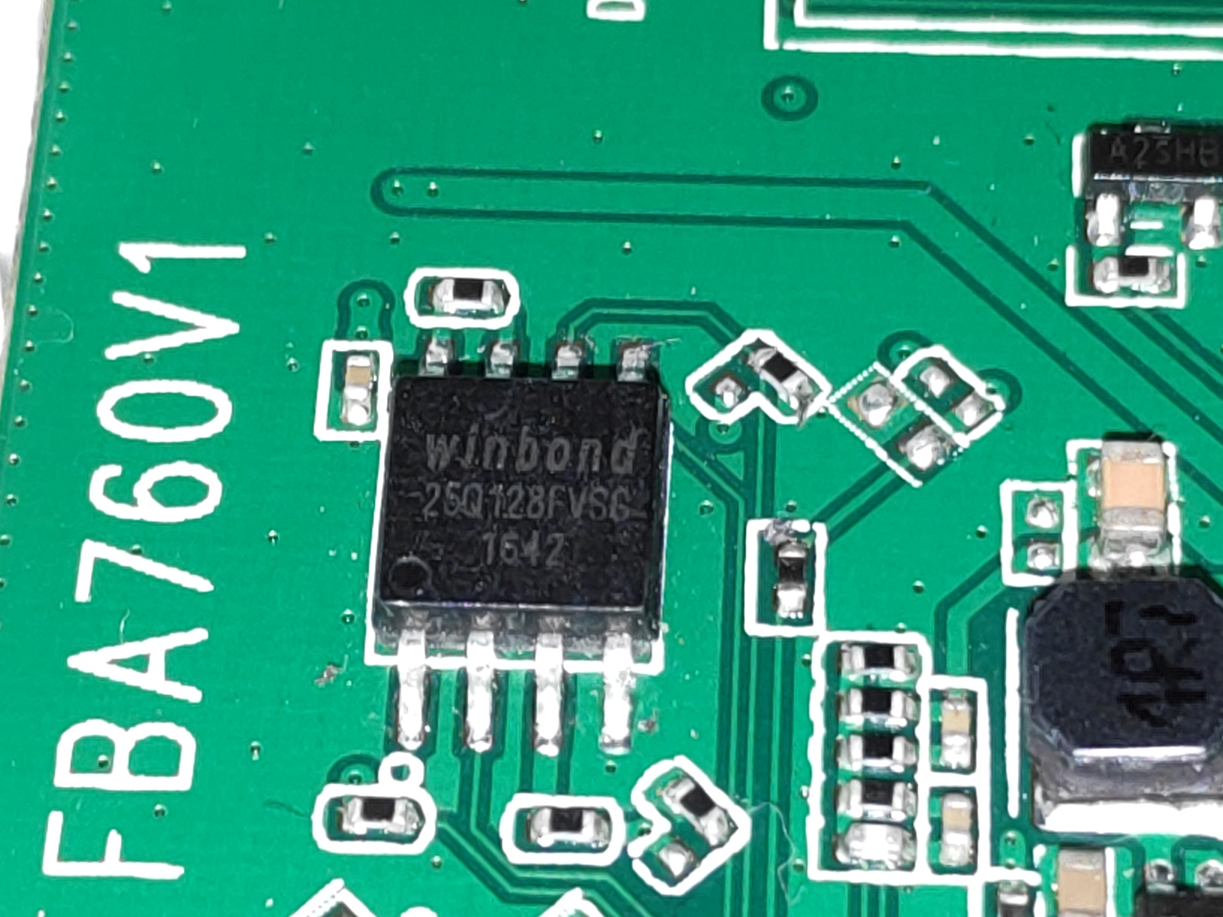
Gotcha it’s Winbond 25q128fvsg from datasheet Figure 1a we now know exact pin numbers and what they do. And basically location of cirular notch is exactly where pin 1 is situated (bottom left in above picture).
Now power on your target device and put SOIC8 adapter clip in such way that red wire lands on pin1 of EEPROM. And start making connetions on RaspberryPi device according to table below (Number refers to Physical pins):
| RaspberryPi | Winbond EEPROM |
|---|---|
| 24 | 1 |
| 35 | 2 |
| - | 3 |
| 6 | 4 |
| 38 | 5 |
| 40 | 6 |
| - | 7 |
| 1 | 8 |
Check out RaspberryPi pin config
Once done power on your RaspberryPi open terminal and Type following. Please note you should be using official RaspbianOS
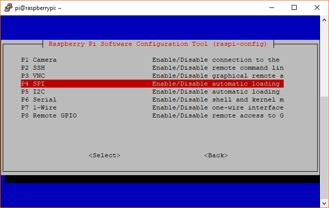
sudo raspi-config
You will be presented with menu, go to Interfacing options and then enable SPI interface and then reboot.
Once done now you have to get software in order to read and write from EEPROM memory, use following command below to get it easily:
sudo apt install flashrom -y
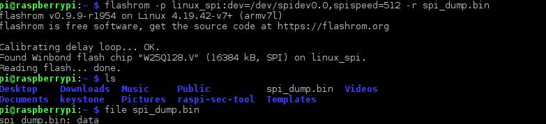
Now you are ready to start reading data from target EEPROM with flashrom
flashrom -p linux_spi:dev=/dev/spidev0.0,spispeed=512 -r filename.bin
Wait few minutes (15-30min approx)
Conclusions
With help of this method you avoid damaging your EEPROM chip and save lot’s time of soldering and desoldering.
Honourable references: