Identifying UART Pins Without a Multi-Meter (PinNinja)
As someone who likes to tinker with hardware, we often find ourselves opening up a device to find UART pins which are originally meant for debugging and testing We often use these to connect to the device. But most of us hit a small snag here.
Snag No 1: More often than not the pins are not labeled.
(So you mean they put those pins there so we can test the device but didn’t tell what pin was what because they didn’t want us to test it? )
Thankfully according to a number of sites, there is simple test with a multi-meter to identify the pins.
Snag No 2: We don’t have a multi-meter.
Okay, so now we have hit a real problem. So naturally I came up with an alternate way to to tackle this. I used my good old trusty Arduino Uno to solve the problem. You can check out the script here.
Step-wise instructions are in the README.md. For now let’s discuss the logic behind it and understand how it works.
For development and testing I used an old router: I-ball Baton 300M extreme High Power Wireless-N Router (IB-WRX300NP)

On looking closely enough the UART pins are on the right side. I chose this device for the sake of research as the UART pins on this device are labeled.
Now I connected the pins to my Uno’s Analog pins A0, A1, A2 and A3 (14, 15 ,16, 17).
- A0 – GND – 14
- A1 – VCC – 15
- A2 – TX – 16
- A3 – RX – 17
Identifying Ground
Now to start identifying the pins I powered on my router and started monitoring the analog readings of each pin using the following code
void valdump(){
int i = 0;
      for(i = 0; i < 4; i++){
          int j=0;
          delay(200);
          Serial.println(inPin[i]);
          for(j = 0; j < 20; j++){
                int val=analogRead(inPin[i]);
                Serial.print(val);
                Serial.print(" ");
                delay(10);
          }
          Serial.print("\n");
       }
  }
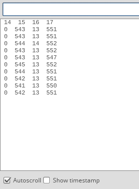
On studying this dump I realized the value of ground (14) remains 0 . Therefore,we can identify ground by simply finding the pin with the reading as 0 or with the lowest current.
Note : A single low value is not enough as the value of TX and RX often fluctuate to 0
Identifying VCC
On further reading into UART revealed that VCC and GND are connected via a capacitor.
Which means if we were to apply a voltage across these pins a small current will flow while the capacitor is charged (No actual current will flow through the ground as a capacitor does not let electricity to flow but a movement of charges will be detected as current). We can use this to our advantage. Now that we have already identified GND we can monitor the analog readings of ground by setting the rest of the pins to high one by one. Since it takes very less time for a capacitor to be charged I reduced the delay to 3 milliseconds from 10.
Identifying RX and TX
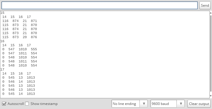
Now that two of the pins have been eliminated. We can go back to the dump we used to find VCC with. The idle state of RX is high. This can be observed in the dump.
The Pin 17 is high whereas 16 is low (it can fluctuate). Therefore this property can be used to Identify RX however we cannot say for sure.
UART packs a signal with a start bit, parity bit and a stop bit which indicates the beginning, health and end of the signal.
We can use this to our advantage. By sending a start bit the current in the RX pin should drop to 0 to read the input signal, and we should be able to identify RX.
The start bit in UART is 0.
Now to see this in action. I set RX (17) to 0 and then dumped the analog readings
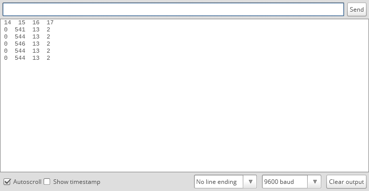
Sure enough the value of Rx dropped to 0. Now Tx can be identified through the process of elimination.
Conclusion
Now that we know what kind of patterns each pin shows. We use it to identify the pins. i.e A simple script (PinNinja) can identify the pins and will tell you which pin is connected to which analog pin. (This has been tested on a couple of routers and on an ESP8266).